NOTE: Keep In Mind That Reading and Understanding P and ID Is a Core Topic of Instrumentation, Any Instrumentation Engineer or Technician Should Know This Stuff, Before They Enter Any Plant as a Team Member.
P&ID is Piping and Instrumentation diagram. It is a detailed diagram used in the process industry which shows the piping and process equipment along with the instrumentation and control devices. A Process Plant Will Have a Number of Similar Process Instruments and a Bunch Of P&Id Drawings.
If a technician has To Find a P&Id Drawing Associated with a Particular Instrument Then He Has to Note Down the Tag Number Of that Particular Instrument and Check a Document Called Instrument Index to Get the Exact P&ID Number Associated with that Instrument.
What is Instrument Index.
Instrument Index Is a Document Containing List of Instruments Within a Plant.
Instrument Index Shall Include :
Tag Number of all Physical Instruments and Pseudo Instruments Like DCS Indications.
This Is a Typical Instrument Index Document.
This Instrument index Gives us Information about:
Now We Have the Exact P and ID Drawing Corresponding to the Particular Instrument with Us.
The First Page Of P&ID Is Naturally the Cover Page.
The Second Page Is the Index Sheet.
The Index Sheet Of P&ID Gives Us an Idea about :
1.The Drawing Number,
2.Description Of P&ID and
3.The Revision Number of The Drawing.
The First Drawing Made is Represented as R0. Any Change Made in the Drawing from R0 is Represented as R1, respectively and the Further Changes will be Represented as R2, R3 And So On.
P&ID Symbology Legend.
Next Sheet Is the P&ID Symbology Legend.
This Sheet Gives Us an idea about almost all the Symbols and Abbreviations Used in this P&ID.
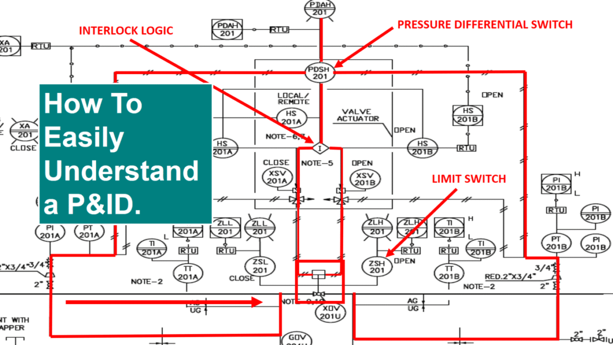
This below shown pic Is of a Typical P&ID.
Parts of a P&ID Drawing.
P&ID Drawing Has Mainly Three Parts
The First Is Title and Revision Block
Second One Is Notes Block And the
Third Part Is Drawing and Description Block.
Now Let Us See Each Block in Detail.
This Block Contains,
Title of P and ID Drawing,
Drawing Number,
Company Details and
Revision Details.
This Block Explains Any Special Symbols and Conventions Used on Drawing. It Also Gives Information which Is Necessary to Understand the Drawing.
Now the Last Block Is,
This Block Includes the P&ID Drawing and Its Necessary Descriptions.
Now we will try to Read This P and ID.
This fig shows a Process Flow Tag Which Shows, from Where This Pipeline Is Coming from and the Previous P and ID Number. From This Tag, We Can Understand That, this Pipe Is Coming from Scrapper Launcher.
In this P and ID at The End of The Process Flow Tag We Can See the Line Number.
Which Gives Us the Details About Size, Purpose and Material Classification of This Pipeline Which We Have Already Discussed in Our Previous Chapter.
The Main Line Divides into Two Streams Through a T-Joint as “FLOW TEE” is Mentioned Here, It Is Understood That a Special Type of Fitting Called “FLOW TEE” Is Used in This Pipeline.
Any Special Type of Fittings Used in plant Will Be Clearly Mentioned Like This in a P and ID.
Now We Follow This Mainstream.
Here We Can See a Ball Valve XOV201U In Between the Pipelines. Below This Ball Valve Symbol, It Is Written as “NOTE 9 & 10”.
To Know What “NOTE 9& 10” Is We Have to Check the NOTES Block Which We Had Mentioned Earlier. When You See a “Note” Like this Near to Any Instrument You Have to Check the Notes Block to Get More Idea About That Instrument.
Now We Can See That the Valve Is Fitted with the Limit Switches ZSL and ZSH.
This Limit Switches Shows the Open and Closed Status of the Valve. ZLL And ZLH Shows the Corresponding Running Lights in Local Panel and Control Room.
Now When We See the Actuator of The Valve XOV we Can Understand That the Valve Is a Pneumatic Valve as Pneumatic Lines are entering the Valve.
When We Follow this Pneumatic Lines, We Can See two Solenoid Valves from where the Pneumatic Lines Are Coming.
As CLOSE is Mentioned Near to XSV 201A Solenoid Valve This Valve Is Used to Close the XOV Valve.
As OPEN Is mentioned Near to XSV 201B Solenoid Valve, This Valve Is Used to Open the XOV Valve.
Both The Solenoid Valves Are Connected to a Differential Pressure Switch (PDSH) Through an Interlock Logic which Determines when to Open or Close the XOV Valve.
Differential Pressure Switch Is a Device Which Utilizes a Differential Pressure to Activate an Electric Switch. It Is Used to Sense Pressure Difference between two Points in a System. When We Closely Watch the Differential Pressures Switch, We Can Say That Two Pneumatic Lines Are Connected to It.
The Differential Pressure Between the Upstream and Downstream of the XOV Valve is Used to Activate the Interlock Which Determines Whether to Open or Close the XOV Valve.
The Valve Is Set to Close When the Rate of Upstream or Downstream Pressure Drop Reaches a Predetermined Value.
PDAH Is Indicator Alarm Light in Panel Which Indicates That Differential Pressure across XOV Is High
Leave a Reply